Parametric design is becoming more relevant. Especially as the construction industry is only now becoming more open to the wide use of technology. In recent years we have observed the increase of non-traditional tools targeting the whole construction industry. Increasingly complex structures are designed nowadays, for which traditional design methods are not easily applied. It is during these times that innovations happen. Parametric design tools almost exclusively used by Architects a few years ago are now available for structural and civil engineers. Let's take a closer look at parametric modelling and design.
WHY GO PARAMETRIC?
Generally, companies could benefit from increased productivity by using parametric design. A parametric design workflow helps create, maintain and optimise structural analysis models while keeping the model definition clear and readable. The most common way to design structures parametrically is through Visual Scripting. Grasshopper, a plugin for Rhinoceros (a 3D modelling package), is one of the most widely used visual scripting environments. Likewise, Dynamo offers a similar function for Autodesk Revit. Visual scripts use an algorithm to create various entities (i.e. points, lines and surfaces) in 3D model space. This algorithm follows linear logic and is relatively simple to define in the graphic user environment. Compared with traditional programming languages, a visual script is far more intuitive. Provided the visual script has been robustly created, then changes to the structural topology (i.e. the geometry of the structure) can be carried out extremely quickly.
The most basic workflow is simple – define two points (i.e. nodes), and connect those points with a line. If the location of either points changes, the line will still connect them. The same idea can be applied to creating lists of nodes and lines, ultimately generating a structural system. It is certainly fun to begin visual scripting, and anyone can become quite productive in a short space of time. For example, Figure 1 shows a visual script that generates a 3D space truss for a roof canopy with customised geometry. With practice (and training), this visual script could be created in as little as 15 minutes.
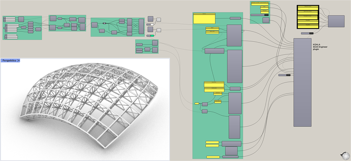
Fig 1 – Visual script that generates a 3D space truss topology (resulting structure topology bottom-left)
Visual scripting offers a readable "script" that may be transferred to most commercial structural analysis software. The scripted model topology (structural geometry and cross-section sizes) can be imported into popular analysis and design software packages by using other software components. These software components are widely available and regularly provided free of charge. Connection to software, such as SCIA Engineer, Tekla Structures, Dlubal, IDEA StatiCa, etc., are available for Grasshopper free of charge. One significant advantage of Grasshopper is openness; anyone with basic programming skills can create a new component to serve a specific need and share it with the community. Of course, advanced programming skill is required to create FEA solvers or analysis tools for complex topics such as real-time analysis of tensile membrane structures (e.g. the Kangaroo plugin), computational fluid dynamics (CFD solvers for wind tunnel simulations), or advanced weather calculations (e.g. the Ladybug plugin). The open nature of visual scripting allows users to choose the most appropriate tools to complete any number of design tasks while using the same scripted model topology. Besides the model topology, the engineer must also add boundary conditions (supports, hinges, loads, etc.) which can all be defined within the visual script. For example, users can automatically loop a SCIA Engineer analysis to optimise the structure while printing result values and running member checks in each iteration. It is worth noting that when working with SCIA Engineer, some settings cannot be defined in the scripted model. For example, mesh settings or selecting the appropriate results to export. In these cases, users could use template project files to predefine these parameters before transforming the scripted model into the analysis model.
CHALLENGING STRUCTURES – AIRPORTS AND STADIA
One of the main applications of the parametric design approach are types of structures that would be too complex to model manually. Stadia, airports, high-rise buildings (or any landmark structure) designed by ambitious architects have one thing in common: highly complex shapes that are often too complicated to model by conventional means within feasible time restraints. Large architectural practices (e.g. Zaha Hadid Architects) use the parametric approach daily. Structural engineers could become very efficient if they learnt to use the parametric model produced by the architects to generate the structural geometry. Parametric design methods allow the engineer to create analysis models of the most demanding projects in minutes instead of months. These models might contain thousands of members, but changes could be implemented, analysed and designed with relative ease.
One of the most recent applications of this approach is the monumental Al Janoub Stadium in Qatar (Fig. 2), where engineers from AECOM used parametric methods to conceptualise and design the structure. The stadium was built for the 2022 FIFA World Cup. It seats 40 000 spectators and will be used up the tournament's quarter-finals. Afterwards, it will be converted to 20 000 seat capacity and used by the Al Wakrah Sports Club. The roof comprises two symmetrical parts, each side composed of three shells. The upper tiers of the stadium were designed to be removable after the tournament. The roof structure, which comprises 185 m propped arches, underwent construction staging design, fire engineering and plate design for the sculpted V-columns supporting the primary arches.
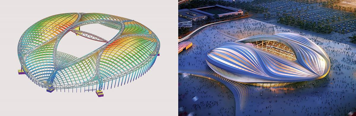
Fig. 2 – Al Janoub Stadium in Qatar [1] Left: Structural analysis model in SCIA Engineer as featured in the SCIA User contest 2020; Right: Architectural visualisation
Creating a landmark stadium that offers a world-class experience was the challenge. Rapid prototyping using parametric design with SCIA Engineer and interoperability with virtual reality environments allowed the engineers to test different solutions and evaluate options to produce a stadium befitting the Architect's vision.
The approach taken to create the parametric model of the Al Janoub stadium is not that different from the space truss example shown before (Fig 1.). The script, however, was indeed more complex, and the designer needed to be in complete control of the data. Usually, such projects are divided into several parts that are connected but modelled by separate partial scripts. In the final steps, all members are merged into a single long list which can be then linked with the structural analysis model.
FROM PARAMETRIC TO GENERATIVE DESIGN
Emerging fields of parametric design are topics of topology optimisation, form-finding and generative design. In all of these cases, the engineer defines the boundaries of the possible solution and then advanced algorithms iteratively find the optimal solution. In generative design, artificial intelligence (AI) is combined with parametric design to select the best structural form. For pragmatism, the AI is not totally free to find the optimal form; the engineer will need to define some boundary conditions to guide the AI. Typically, these conditions are defined support areas and the volumetric domain in which the structural form can exist. Generative design algorithms can often lead to one of a kind results because structures are optimised for their unique conditions. Interestingly, structures optimised this way often resemble shapes found in nature (Fig. 3).
Structural forms produced by the generative design very often resemble trees. If you examine the "superstructure" of a tree, the trunk is strongest at its base as this is the spot where all the force and moment due to leaves, branches and wind loads are the most substantial. The trunk divides into large branches, continuing to divide into smaller and thinner branches. Eventually, optimally shaped leaves at the branch ends cover as much area as possible to catch sunlight. Evolution drives trees to be as efficient as possible, and the forms that develop are directly linked with the conditions where the tree species exist. The same principles can be applied to design, architecture and engineering. Similar efficiency may be observed in long-span bridges, where material utilisation largely drives structural design. Efficiency has always been a fundamental question in structural engineering.
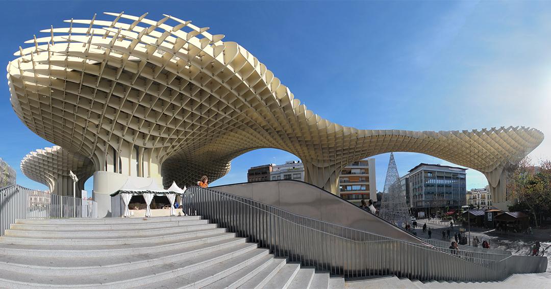
Fig. 3 – Typical case of generative design. [2]
Of course, generative design may be used in other areas besides the design of natural shapes and organic structures. It could be used to find an optimal arrangement of flats in a multistorey building or optimise whole urban areas to be more convenient for the inhabitants. Adding a layer of AI or machine learning on top parametric design algorithms allows the engineer to compare vast amounts of potential design solutions and practically select the most efficient scheme. This process would not be realistically possible to do using traditional engineering methods.
PARAMETRIC BRIDGE DESIGNS
One apparent sector of structural engineering where projects might benefit from parametric methods is bridge design. When designing longer and longer spans, the structural system must be very efficient to remove unnecessary structural mass. This is very much aligned with the parametric design approach. The profile and plan curvature of a bridge is often determined by the alignment, profile and cross-section of the carriageway or railway it supports. When the bridge curvature is significant in plan or profile, creating an analysis model often becomes tedious and error-prone. This is especially true for bridge forms (e.g. trusses, suspension or cable-stayed) that are generally composed of many elements. Parametric design offers a more efficient method to create that same analysis model in less time. Moreover, there is potential to generate the analysis model directly from the highway model if it is also created parametrically.
Additionally, a significant benefit of parametric bridge design is the option to reuse existing scripts, which is a great productivity advantage. Since bridges are generally quite similar, reusing scripts from previous projects of the same bridge type could save a lot of the design time. Remember that good scripts rely on satisfying design conditions and not exclusively exact numbers. The suspension bridge shown in Figure 4 below is in the Czech Republic. After the parametric model was created, it was transformed into an analysis model in SCIA Engineer by a Grasshopper plugin - Koala. The FE analysis and design check of the steel members was then completed in SCIA Engineer.
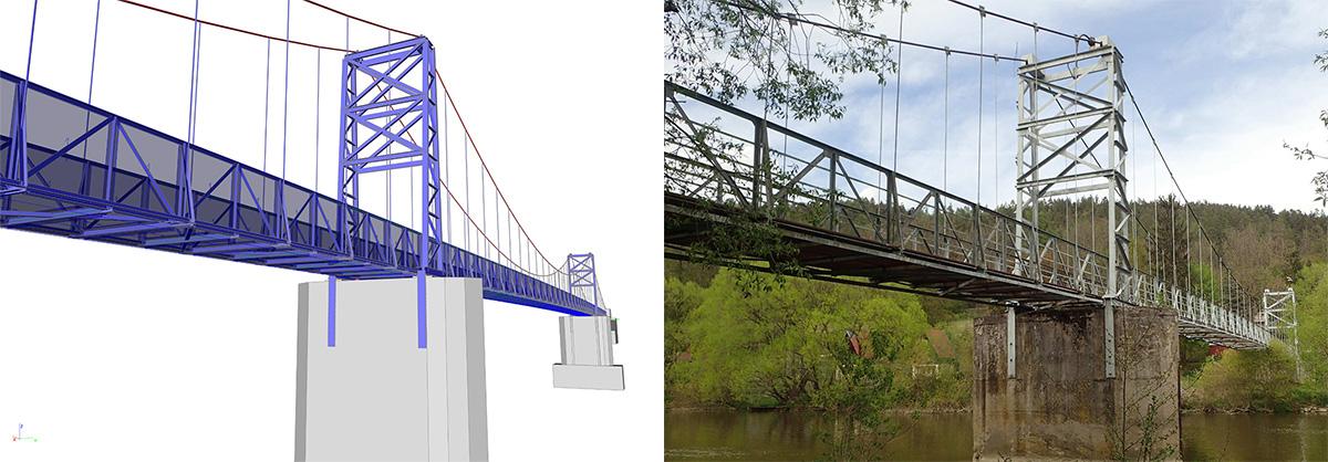
Fig. 4 – Sázava footbridge modelled by visual scripting and was featured in the SCIA User contest 2020. [3]
Various bridge types can be modelled and designed parametrically, but how documentation is provided to authorities, stakeholders, and the construction team might be transformed by connecting BIM software tools to the parametric model. Combining these tools enables designers to produce models rich in data that can be used during the construction and maintenance phase of the bridge lifecycle.
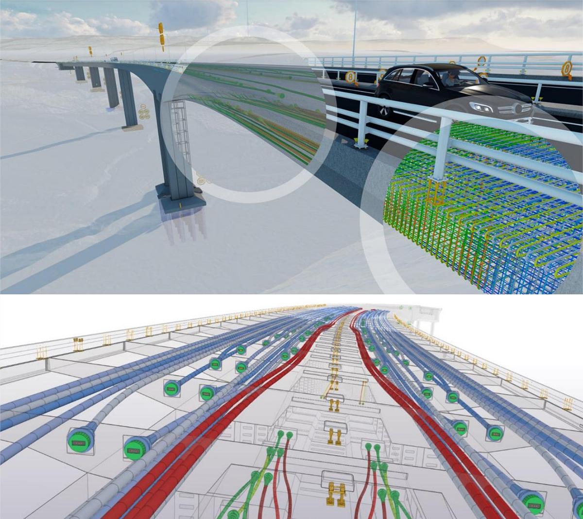
Fig. 5 – Visualisation of the BIM model of the Randselva Bridge, Norway. [4]
Having a central model helps resolving clashes between reinforcement bars, prestressing tendons and other service routes on the bridge. This process mitigates and minimises potential clashes on-site that would otherwise cause delays in the construction process. The country that seems to be the furthest in this development is Norway. The Randselva Bridge was designed in 2016 by the road administration of Norway. The construction was based on an extensive BIM model. The model contained information including the reinforcement of every construction phase, railing and road surface finishes. The as-built BIM model was also archived by the Norwegian road administration as comprehensive information for maintenance and operational purposes. In fact, nowadays, most bridges in Norway are submitted to authorities and contractors in the form of a BIM model. Undoubtedly, other countries will follow suit.
CONCLUSIONS
Parametric design will surely change how engineers approach and tackle complex structural projects. Currently, its power is most utilised in the design of wild architectural structures. Yet, it offers a fast method for engineers to create analysis models for complicated structural geometries, with the added advantage of being able to keep up with project changes. Also, for the majority of bridge engineers, it is a viable solution to automate the design process whilst potentially saving even more time by better reusing previous work from completed projects.
REFERENCES
[1] https://www.scia.net/en/company/references/projects/al-janoub-stadium
[2] https://bdaa.com.au/generative-design-generates-results/
[3] https://www.scia.net/en/company/references/uc-books
[4] https://e-mosty.cz/wp-content/uploads/e-mosty-Sept21.pdf